Understanding the Electric Field from a Charged Half-Ring
Written on
Chapter 1: Introduction to Electric Fields
The challenge at hand involves a half-ring with a radius ( R ) and a total charge of ( +Q ). We need to determine the electric field vector at the center of this circular setup. Additionally, we will tackle the more complex task of calculating the electric field at various other positions.
To start, calculating the field at the center isn't overly complicated, but assessing it elsewhere will require numerical methods—I'll be utilizing Python for this purpose, which should be quite engaging.
Electric Field at the Center
Fundamentally, the electric field can be expressed with a single formula relevant to point charges.
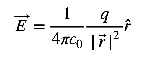
This formula consists of several components: the constant ( frac{1}{4 pi epsilon_0} ), the charge ( q ) in Coulombs, and ( r ), which is the distance vector from the charge to the location where the field is assessed. Remember to square the distance, meaning you must first calculate the magnitude of the vector, as vectors cannot be squared directly. The notation ( hat{r} ) indicates a unit vector that shows the direction of the distance vector ( r ), ensuring that the resultant electric field remains a vector.
Since we have only one expression for the electric field, we can treat the half-ring as a collection of infinitesimally small point charges. We can then compute the electric field generated by each point charge and sum them up.
It's important to remember that the electric field is a vector quantity, so we must retain the vector characteristics of each component of the total electric field. I have an effective strategy for visualizing this, which I will illustrate next.
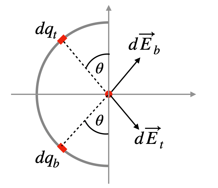
In the diagram, I've depicted two infinitesimal charge elements, both denoted as ( dq )—one labeled ( t ) and the other ( b ). Despite their equal distances from the center and identical charge values, they generate electric fields of the same magnitude but at different angles. When we combine these two vectors, only the x-component remains.
The x-component of the electric field for each segment of charge can be expressed as follows:

In this expression, the angle ( theta ) corresponds to the angle from the x-axis. This shows that the x-component is dependent on the sine of ( theta ). This simplification allows us to work with a scalar value, making calculations easier.
Since each charge segment on the half-ring is consistently ( R ) distance from the center, we can represent the x-component of the electric field generated by each charge as:

As we traverse the half-ring, the only variable changing in this expression is ( theta ). Therefore, we can integrate both sides of the expression.

The left side represents the x-component of the electric field, while the right side, though simpler, poses an issue as ( dq ) varies with ( theta ). To facilitate integration, we convert ( dq ) to ( dtheta ), and we must account for the factor of 2 since we are integrating halfway and must consider the symmetric counterpart.
The total length of the half-ring is ( pi R ). Assuming a uniform charge distribution, the linear charge density can be expressed as:
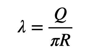
Here, ( Q ) denotes the total charge. The length of the infinitesimal segment of the half-ring at position ( theta ) can be described as:
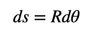
Utilizing this length along with the linear density allows us to derive an expression for the infinitesimal charge segment.

Now, we can substitute this into our earlier integral.

At last, we can perform the integration.

Notice that evaluating the cosine function at the limits yields 1. Consequently, we can express the total electric field as:

This presentation of vectors is my preferred method for structuring content.
Before we proceed, we should verify that this value has appropriate units. Indeed, it maintains the correct electric constant and incorporates charge divided by the square of distance, confirming its validity.
Typically, I would also examine limiting cases, but in this scenario, we're at the center of a half-circle, meaning there's no position further from the center in that regard. If we were to modify the limits of integration for a complete circle, we could demonstrate that as the angular segment approaches zero, the electric field converges to the formula for a point charge. You may consider that as an exercise.
Electric Field at Other Locations
What about determining the electric field at other positions? In principle, this isn't exceedingly difficult. We can still derive the electric field from small segments on the ring.
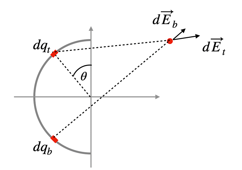
While I can still analyze pairs of segments, this method becomes less effective since the magnitudes of the electric fields generated by these segments are no longer equal, and their angles lack symmetry. Although an expression can be formed, the resulting integral becomes complex.
Instead, let's approach this numerically. A numerical solution involves breaking the problem into a finite number of segments and calculating the electric field vector for each segment. The results are then summed.
This method is straightforward enough for a computer to handle. Here’s the plan: divide the ring into ( N ) segments (where ( N ) is any number you prefer), treat each as a point charge, compute the electric field from each segment, and aggregate the results.
For instance, if I divide the ring into five segments, it will appear like this:
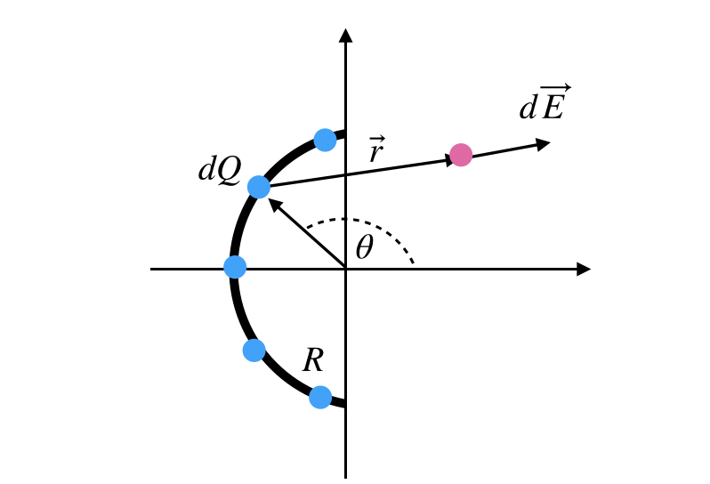
Suppose the total charge on the ring is 5 nC and its radius is 0.01 meters. I will calculate the electric field at the coordinates ( <0.03, 0.04, 0> ) meters.
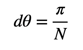
To find the location of each segment, I’ll express it in terms of an angle ( theta ). If I position the first segment at ( frac{pi}{2} ), the subsequent segment will be placed at an angle increment away. The angular step size can be calculated as follows:
Here’s how it looks with seven segments.
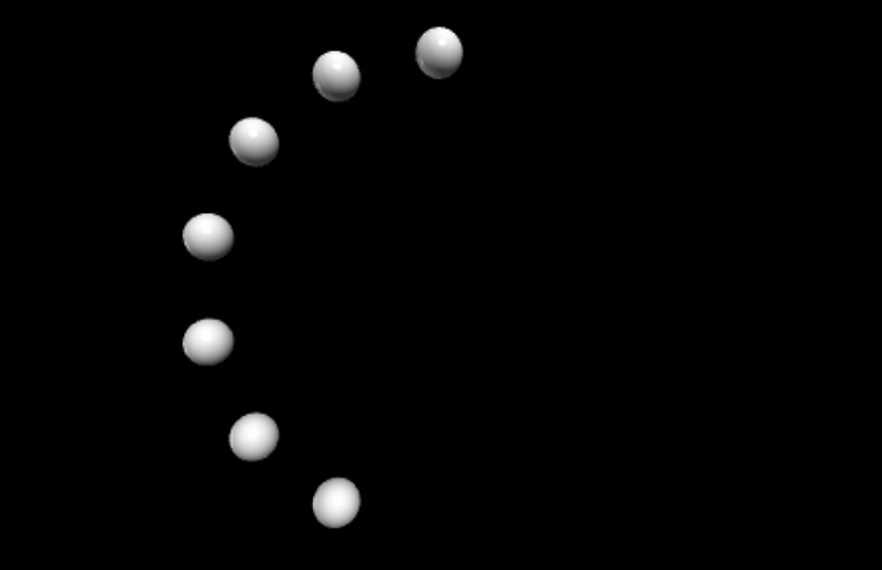
I’ll provide the code (link to code) for generating these points. Note that I am utilizing VPython Glowscript for visual representation. While this might appear strange with just seven points, increasing the count to ( N = 100 ) will yield a better depiction.
To summarize the approach: begin at ( theta = frac{pi}{2} ) and place a charge there. Calculate the charge value (which is ( frac{Q}{N} )). Determine the vector ( r ) from that charge to the desired electric field location, in this case, ( <0.03, 0.04, 0> ) m. Use this vector to compute the small portion of the electric field and add it to the cumulative total. Move to the next charge location and repeat the process.
Here’s the relevant code.
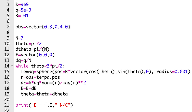
This results in the output shown below:

Let’s discuss the code further. Line 13 reveals the need to determine the charge for each segment—this is contingent upon the total number of segments. Line 12 emphasizes the necessity of accumulating the total electric field from each segment, starting from zero. In line 15, I have designated the point charges for easy reference. However, in this method, there is only one charge that simply shifts position. Line 16 involves calculating the vector ( r ) from a segment to the observation point, while line 17 computes the electric field resulting from a point charge.
Now, let’s conduct a verification. If the observation point is at the origin, I could perform this calculation both analytically and numerically, expecting the results to align closely.
When I divide the ring into just seven segments, the outcome is:

That’s impressively close. What if I increase ( N ) to 100?

The results are not merely close—they’re exceptional.
The inserted YouTube videos and their descriptions would be as follows:
In this video, we explore how an electric field is generated by a charged half-ring, detailing the mathematical principles involved.
This video discusses the electric field of a semi-circle with both uniform and non-uniform charge densities, providing insights into the complexities of charge distribution.